Not step or extension, but an array of railroad switches. So, all my non-railroady friends can return to their regularly scheduled program...
I started building my model railroad 35 years ago. One of the first parts was a flat classification yard. I hand laid the track, including nearly all the switches from kits. They had the points soldered to a solid metal throw bar and relied on the points to route power to the frog. Standard ground throws did not provide enough throw and force to make reliable contact.
If you add in that lining a route on the yard ladder can require throwing several switches to my propensity to run through misaligned switches, then the chance for failure it rather high.
So, I decided to replace all the ground throws with Tortoise switch machines and use a rotary switch to determine the route through the ladder.
Simple concept. But how? When twin coil switch machines ruled the road, modelers would often use diode matrixes and a capacitive discharge to do this. How about a diode matrix for Tortoises?
I found this: https://www.trains.com/mrr/how-to/build-model-railroad/design-procedure-for-yard-ladder-control-using-tortoise-switch-motors/ Where you use the internal contacts on the switch machines to handle some of the logic.
Since I was going to make a big mess drilling holes under the switches for the switch machines, I decided to convert the switches to a more DCC friendly arrangement. I used copper clad ties to replace the original solid metal throwbar and just filed through the copper in the middle of the tie. I used the second set of contacts on the machines to power the frog.
Since this was going to be a lot of wiring, I decided to use terminal strips to standardize the wiring for each machine and to make it easier to fix mistakes.
I made two fundamental mistakes. One was not paying attention to the Tortoise pin-outs for the internal contacts. The second was getting the "reverse" and "normal" backward on several because of how I mounted them under the layout. This meant that my great planning to solder most of the switch machine terminal ahead of time on the work bench went for naught and I had to do soldering under the layout. Yuck.
Because of the way the points were soldered to the throw bar, the Tortoises needed stiffer wire to develop the right combination of force and throw to move the points. I also had to cut some relief in the ties near the points to reduce the friction throwing the switched.
The control panel has LEDs to indicate which track the ladder is lined for as well as some push buttons to manually control the mainline - to yard crossover that is powered by a DCC accessory decoder. (NCE "Snap-it")
Here are some pix.
 |
| Yard ladder |
 |
| Converted switch kit |
 |
| Terminal strips |
 |
| Control Panel |
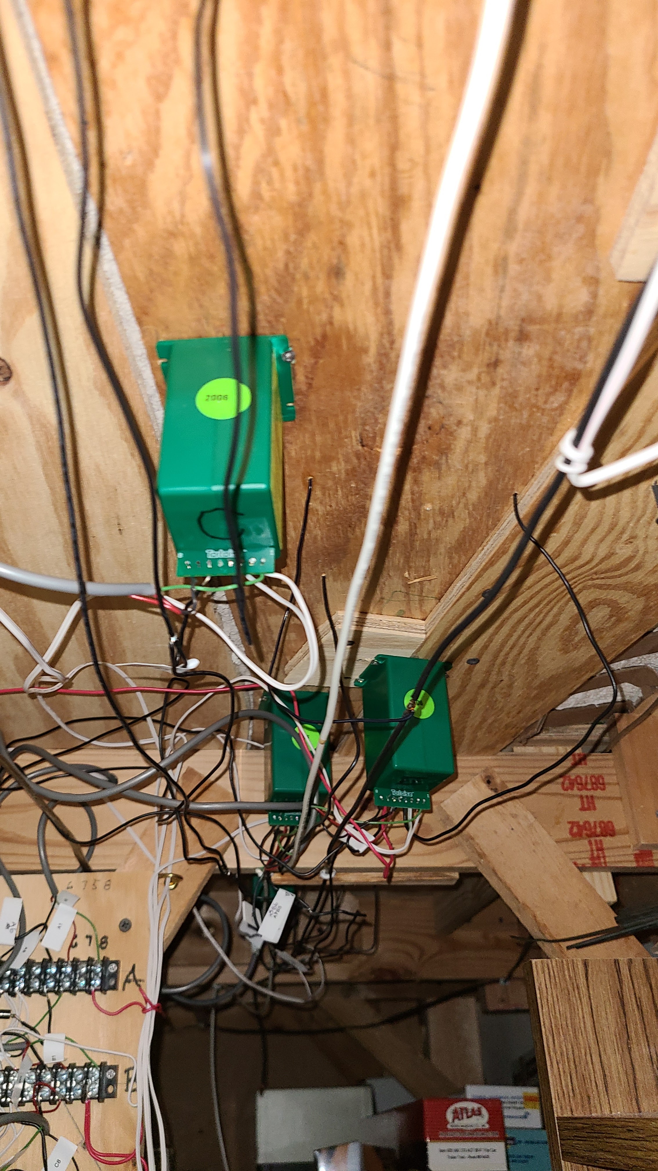 |
| Some of the switch machines |
 |
| Panel wiring |
Has your layout met the PTC deadline?
ReplyDeletePermanently stuck in 1985-95...I stil run cabooses!
ReplyDelete